Military Shock & Vibration Tests of Large Format Displays
Metromatics commissioned a NATA Accredited Sydney Engineering Test House to carry out the necessary MIL-STD Shock and Vibration Testing on a Prototype version of their MetroSpec Large Format LCD Display to be delivered for Australian Defence Navy Contract.
The purposes of the tests were:
- Reveal and identify mechanical weaknesses and/or structural degradation of the prototype
- Determine the ability of the test specimen to perform its function without serious degradation after being subjected to the specified test severities.
The Product:
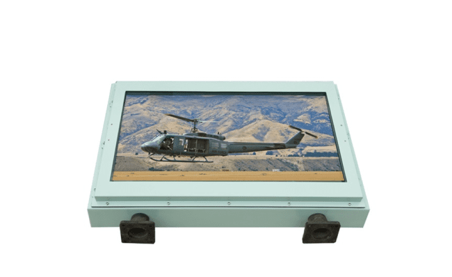
Test Item: MetroSpec Large Format Display 42” with 4 Rubber Shock Mounts
Model No: MS42500HDRAXXXXXXR
Test Equipment Used:
Nationally Traceable Calibrated Test Equipment Used consisted of:
Vibration Testing: Hydraulic Shaker, Power Amplifier, Vibration Controller, 4 x Accelerometers, 2 x Charge Amplifiers
Shock Testing: Shock Machine, Incline Shock Machine, Oscilloscope, 4 x Accelerometers, 1 x Charge Amplifier
1.1 Vibration Tests
The test item was vibration tested in accordance with the following standard:
MIL-STD-167-1A Mechanical Vibrations of Shipboard Equipment (Type I – environmental and Type II – Internally exited) as per Contract Request
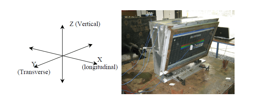
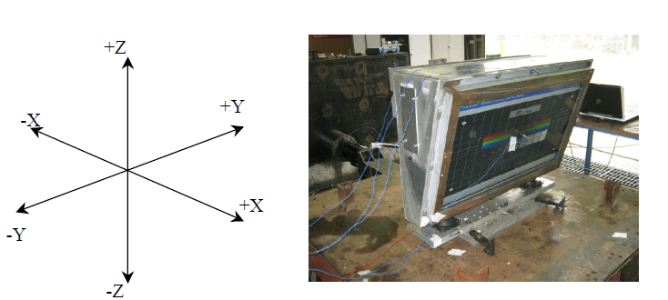
Vibration tests of Z, X & Y Axis
1.1.1 Exploratory Vibration Tests
Vibration type: Sinusoidal sweep
Frequency Band: 4Hz – 18Hz
Vibration Profile: 4-18Hz – 0.51mm
Sweep Rate: 4.02 Hz/min
No. of Sweeps: 1 per axis
No. of axes: 3 (X, Y, Z)
1.1.2 Variable Frequency Tests
Vibration type: Sinusoidal sweep
Frequency Band: 4Hz – 18Hz
Vibration Profile: 4-15Hz – 1.53mm
15-18Hz – 1.02mm
Sweep Rate: 0.2 Hz/min
No. of sweeps: 1 per axis
No. of axes: 3 (X, Y, Z)
1.1.3 Endurance Test
Vibration Type: Fixed Frequency
Test Frequencies: Selected from results of exploratory vibration and variable frequency tests in accordance with MIL-STD-167-1A, section 5.1.2.4.6 Resonant Frequencies of the resilient mounts and surrounding ±2Hz bands excluded from selection.
Vibration Profile: 4-15Hz – 1.53mm
15-18Hz – 1.02mm
Duration: 2 hours per axis
No. of axes: 3 (X, Y, Z)
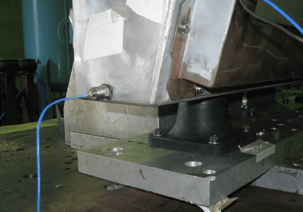
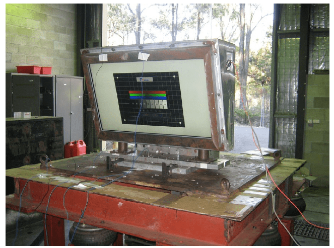
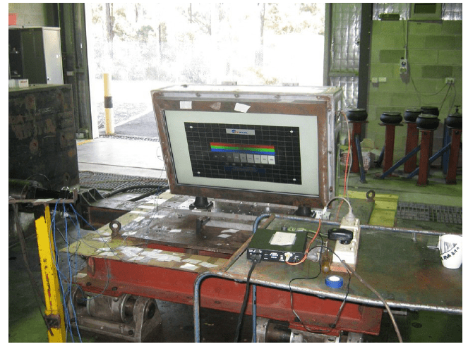
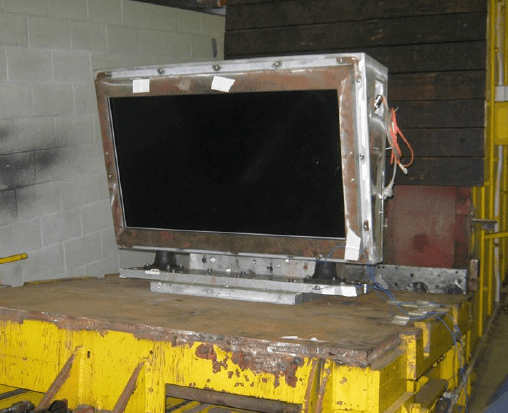
Test Configuration
The prototype was attached onto a L-shaped aluminium fixture by its normal mounting method. The fixture was designed to replicate the Large Format Displays real life mounting configuration on the Naval Vessel. The whole assembly of fixture and prototype was bolted onto the Vibration table allowing exposure to vibration along all three axes.
Set-backs
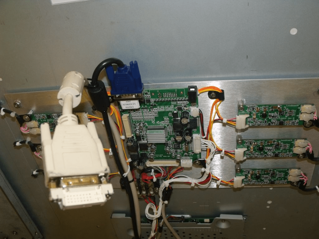
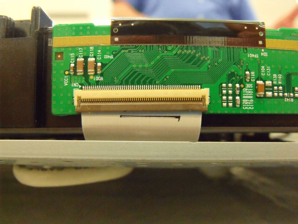
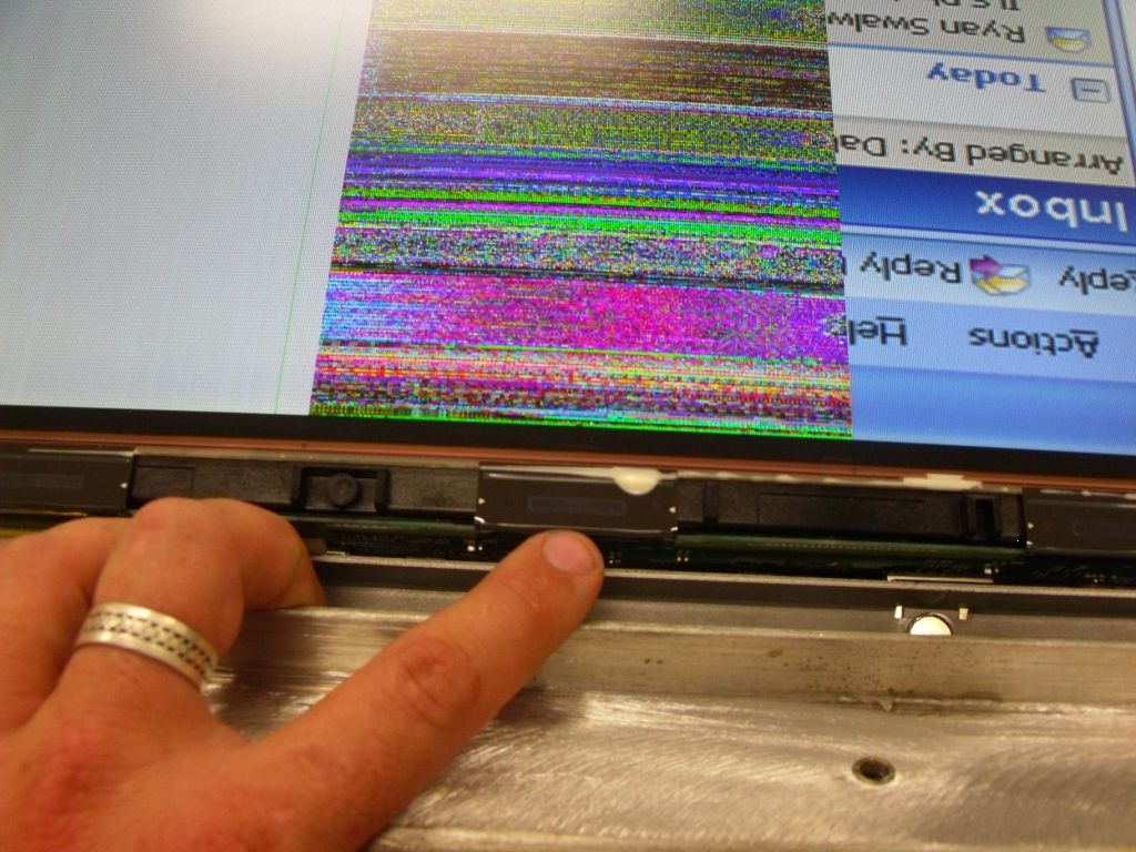
The prototype was initially submitted for vibration testing with the rubber shock mounts at each mounting point. However, Variable Frequency Test in this configuration resulted in functional failure of the test item due to the excessive displacement during sweep through natural frequencies of resilient mounts. The display lost some image quality due a ribbon cable coming loose from the PCB which contributed to a DVI socket breaking free.
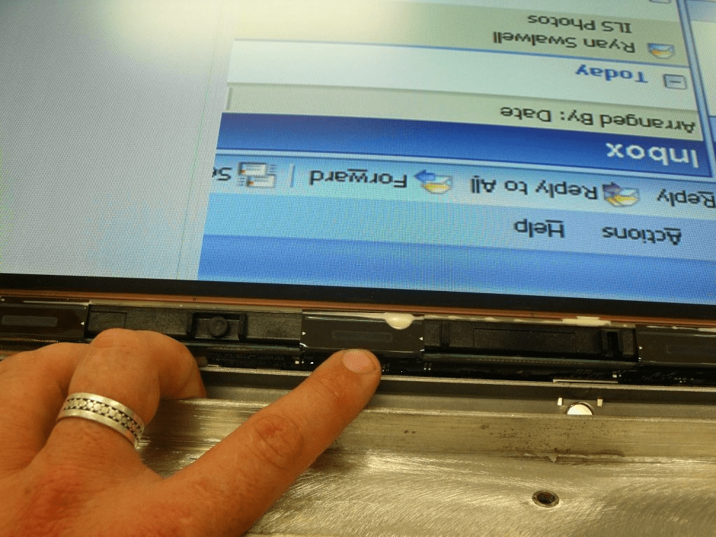
Modifications
Modifications were made internally to correct this issue. This included
- Lengthening the Gear Plate – attaching vertical mount channels at either end which provided extra support to centre section of the panels rear cover.
- Additional Mounting Piece for the DVI and VGA Connectors – this provided better support of the sockets and the extra lance points allowed the video cable to be tied down.
- Modification to mounting of Ribbon Cables – with the addition of 3M VHB tape to the back of the column driver, cable mounting points and extra foam support added to the top of the contact area of the ribbon cable. It prevented the PCB from moving around and possibly destroying the panel ribbon cables. Also Dow Corning 3145 RTV (MIL-A-46146) Silicone was applied to the top edge of the panel ribbon cable to support the ribbon cable junction on the LCD panel.
Re-test Vibration
The prototype was returned to the Test House after it had undergone appropriate design modifications. Subsequent testing was conducted under a slightly different configuration which would still meet the required Military Standard.
- Exploratory Vibration Tests conducted with resilient mounts fitted
- Variable Frequency Tests conducted with resilient mounts removed
- Endurance Test Conducted with resilient mounts removed and tested at the equipment resonant frequencies only
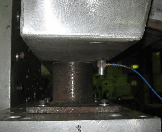
Therefore, the variable frequency and endurance tests, the resilient (shock) mounts were replaced with rigid “dummy” mounts made out of steel but with identical dimensions and bolt patterns as the original rubber units. Accelerometers measuring the test item were installed – above the lower left hand side mount; above the upper left hand side mount; middle of the test item’s side facing the direction of vibration (Z on Top Plate and Side plates for X and Y).
Video 7.6hz 2nd axis_2avi – shows fault on video
1.2 Shock Tests
The test item was shock tested in accordance with the document supplied with the contract. The prototype was subjected to the classical shock test (half-sine pulse) to the parameters specified in the document.
Shock Tests of Z, X & Y Axis
1.2.1 Vertical Axis (Z)
Test Type: Mechanical Shock
Shock Pulse Profile: Half Sine
Amplitude: 17.7g
Duration: 29ms
No. of shocks: 1 per direction
No of directions: 1 (±Z)
1.2.2 Longitudinal Axis (X)
Test Type: Mechanical Shock
Shock Pulse Profile: Half Sine
Amplitude: 15.3g
Duration: 30 ms
No. of Shocks: 1 per direction
No. of directions 2 (+X, -X)
1.2.3 Transverse axis (Y)
Test Type: Mechanical Shock
Shock Pulse Profile: Half Sine
Amplitude: 10.6g
Duration: 36ms
No. of shocks: 1 per direction
No. of directions: 2 (+Y, -Y)
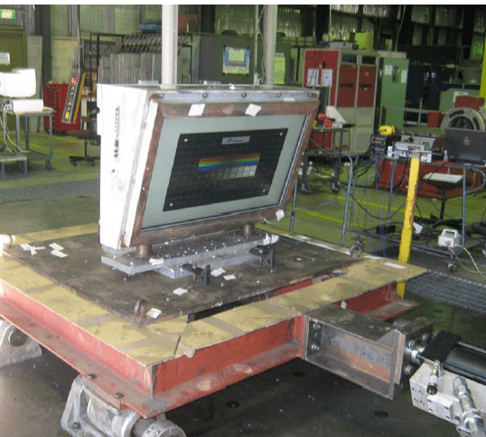
Test Configuration
The prototype was attached onto a L-shaped aluminium fixture by its normal mounting method. The fixture was designed to replicate the Large Format Displays real life mounting configuration on the Naval Vessel. The whole assembly of fixture and prototype was bolted onto the Shock table allowing application of shock in five directions.
The prototype was subjected to shock testing fitted with the rubber resilient mounts at each mounting point. The accelerometers measuring the response of resilient mounts were located above the lower left hand side mount and above the upper left hand side mount.
Test Results
This section outlines the results of the Vibration and Shock Tests carried out on the Prototype.
Pre Test Check
Initial Visual Examination of the Prototype showed no physical damage on the unit. Operational Examination revealed no abnormalities and the unit was functioning correctly.
1.3 Vertical Z Axis
1.3.1 Exploratory Vibration Test
Summary of Vibration Resonances observed during the Exploratory Vibration Test of the Z-Axis.
| Resonance No. | Frequency (Hz) | Gain (g/g) |
| 1 | 9.4 | 8.92 – Lower RM
4.59 – Upper RM 9.2 – Top Plate |
| 2 | 12.9 | 9.91 – Lower RM
9.29 – Upper RM 7.89 – Top Plate |
The Visual examination after, showed no physical damage to the test item.
Test Item was found to be functioning correctly during and upon completion of the test
1.3.2 Variable Vibration Test
No significant resonate frequencies were identified during variable vibration test in Z-axis.
The Visual examination after, showed no physical damage to the test item.
Test Item was found to be functioning correctly during and upon completion of the test
1.3.3 Endurance Test
The vibration resonances observed during Exploratory Vibration test were identified as natural frequencies of resonant mounts and as such were excluded from selection of test frequencies for Endurance Test.
Since no other significant resonant frequencies were identified during variable frequency tests, the Endurance was conducted at maximum frequency of 18 Hz for a period of 2 hours.
The Visual examination after, showed no physical damage to the test item.
Test Item was found to be functioning correctly during and upon completion of the test
1.4 Transverse (Y) Axis
1.4.1 Exploratory Vibration Test
Summary of Vibration Resonances observed during the Exploratory Vibration Test of the Y-Axis.
| Resonance No. | Frequency (Hz) | Gain (g/g) |
| 1 | 7.68 | 21.14 – Lower RM
26.93 – Upper RM 24.29 – Top Plate |
| 2 | 13.22 | 4.775 – Lower RM
0.465 – Upper RM 2.091 – Top Plate |
The Visual examination after, showed no physical damage to the test item.
The test item functioned correctly upon completion of test.
1.4.2 Variable Vibration Test
No significant resonate frequencies were identified during variable vibration test in Y-axis.
The Visual examination after, showed no physical damage to the test item.
The test item functioned correctly upon completion of test.
1.4.3 Endurance Test
The vibration resonances observed during Exploratory Vibration test were identified as natural frequencies of resonant mounts and as such were excluded from selection of test frequencies for Endurance Test.
Since no other significant resonant frequencies were identified during variable frequency tests, the Endurance was conducted at maximum frequency of 18 Hz for a period of 2 hours.
The Visual examination after, showed no physical damage to the test item.
The test item functioned correctly upon completion of test.
1.5 Longitudinal (X) Axis
1.5.1 Exploratory Vibration Test
Summary of Vibration Resonances observed during the Exploratory Vibration Test of the X-Axis.
| Resonance No. | Frequency (Hz) | Gain (g/g) |
| 1 | 9.57 | 7.52 – Lower RM
2.01 – Upper RM 2.06 – Top Plate |
| 2 | 12.08 | 14.51 – Lower RM
10.88 – Upper RM 12.17 – Top Plate |
The Visual examination after, showed no physical damage to the test item.
The test item functioned correctly upon completion of test.
1.5.2 Variable Vibration Test
No significant resonate frequencies were identified during variable vibration test in X-axis.
The Visual examination after, showed no physical damage to the test item.
The test item functioned correctly upon completion of test.
1.5.3 Endurance Test.
The vibration resonances observed during Exploratory Vibration test were identified as natural frequencies of resonant mounts and as such were excluded from selection of test frequencies for Endurance Test
The Endurance was conducted at maximum frequency of 18 Hz for a period of 2 hours.
The Visual examination after, showed no physical damage to the test item.
The test item functioned correctly upon completion of test.
Video: 9.5hz 1st axis.avi & 9.36Hz 3rd axis. avi
Shock Tests
1.6 Longitudinal (X) Axis
| Dir | Lower Reference (amp./dur.) | Lower Response (amp. / dur.) | Upper Reference (amp. / dur.) | Upper Response (amp. / dur.) | Comments |
| +X | 15.5 g / 35 ms | 12.2 g / >40 ms | 17 g / 32 ms | 15.3 g / >40 ms | No apparent damage and test item functional |
| -X | 15.8 g / 36 ms | N/A | 16 g / 35 ms | 18 g / 38 ms | No apparent damage and test item functional. Lower RM Bottomed |
Video: 14.5Hz 1st axis avi
Responses recorded by accelerometers located on test item indicated that bottoming out of lower resilient mount occurred during the application of shock in –X direction. The Visual examination after, showed no physical damage to the test item.
The test item functioned correctly upon completion of test.
1.7 Transverse (Y) Axis
| Dir | Lower Reference (amp./dur.) | Lower Response (amp. / dur.) | Upper Reference (amp. / dur.) | Upper Response (amp. / dur.) | Comments |
| +Y | 10.5 g / 38 ms | 9 g / >60 ms | 12 g / 38 ms | 8.5 g / >60 ms | No apparent damage and test item functional |
| -Y | 10.5 g / 38 ms | 8.8 g / 61 ms | 11.5 g / 38 ms | 8.3 g / 74 ms | No apparent damage and test item functional. |

The Visual examination after, showed no physical damage to the test item.
The test item was functioning correctly upon completion of test.
1.8 Vertical (Z) Axis Shock and Vibration Tests on Displays
| Dir | Lower Reference (amp./dur.) | Lower Response (amp. / dur.) | Upper Reference (amp. / dur.) | Upper Response (amp. / dur.) | Comments |
| +Z | 18 g / 29 ms | 16.6 g / 40 ms | 18.5 g / 29 ms | 19 g / 40 ms | No apparent damage and test item functional |

The Visual examination after, showed no physical damage to the test item.
The test item was working correctly upon completion of test.
Conclusion
Vibration Test
The test item met the Vibration Test Criteria MIL-STD-167-1A Mechanical Vibrations of Shipboard Equipment (Type I – environmental and Type II – Internally exited) as per Contract Request for the Single Large Format Display.
Shock Test
The test item met the Shock Test Criteria in accordance with the document supplied with the contract for the Single Large Format Display.
For more information on this application, contact us.